Sheet 004 — 2026
Why is 3D modeling still so complicated?
From a rough idea to a detailed model you can change, reuse, and hand over: where CAD makes the journey harder, and what AI needs to help with.
01 / 12
There is more to designing than making the first shape.
A rough idea and a model someone can build are very different things. Between them are proportions to explore, parts to organize, dimensions to control, details to resolve, and other people’s requirements to accommodate. Then something changes, and those decisions have to keep making sense together.
At the beginning, you want to sketch freely and compare alternatives. Later, you need precision: material thickness, joints, clearances, repeated parts, perhaps a whole family of sizes. Eventually, someone needs to review the design, revise it, or make it. A chair, a piece of equipment, and a building differ enormously, but all can pass through versions of that journey.
CAD software is extraordinarily capable. The difficulty is that each stage can ask us to work differently. A tool that feels immediate while exploring a shape may need extra structure before changes propagate. A powerful parametric model can demand that we plan relationships before we have settled the design. Moving between tools can mean rebuilding information we already had.
There is also the everyday work of operating the application: finding the right command, selecting the right face, understanding which object a value belongs to, and discovering why an edit affected something else. Eventually, you become good at the software. Ideally, some time remains for the design.
The opportunity I care about is this whole process: making 3D modeling easier to enter, richer as an idea develops, and less painful to revise and share. To understand what a different approach might look like, we first need to look at the choices today’s tools ask us to make.
02 / 12
First, learn how the software thinks.
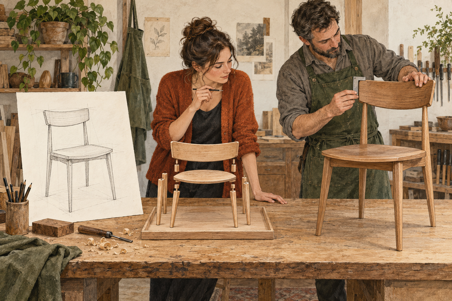
Learning a CAD application means learning its idea of a model. Is this a collection of faces, a sequence of features, a network of rules, or a building element with a type and a host? That choice affects much more than the interface. It determines which actions feel easy and what you must prepare for the next change.
Get a shape down quickly
SketchUp makes drawing and pushing a face into a volume feel immediate. As the model grows, its raw geometry can stick together in ways you did not intend. Groups and components separate parts so you can work on them independently. That solves a real problem, while introducing another thing to manage: which editing context you are inside, and which geometry belongs there.
SketchUp also has configurable components, including Dynamic and Live Components. It would be wrong to say it cannot be parametric. But drawing a cabinet quickly does not automatically establish how its shelves, doors, and hardware should respond when its width changes. Someone has to author that behavior.
Plasticity emphasizes precise solid and surface modeling through direct editing, without requiring a history tree. You can push and pull the shape rather than reconstruct the sequence that produced it. That is attractive while exploring form. Precision and reusable behavior are separate questions, though: changing a face does not by itself describe how a family of related parts should change together.
Make the design remember its decisions
In history-based modeling, as in Onshape, a sketch becomes an extrusion; a later cut depends on that result. Editing an earlier dimension can update the chain. When an upstream change removes a reference, later features can fail. Onshape’s reference-repair tools help compare the broken model with its last healthy state and propagate a replacement. This is useful support for a real responsibility: maintaining the dependencies you created.
Shapr3D combines direct editing with history-based parametric modeling, which makes a strict either-or comparison misleading. Its own direct-versus-parametric tutorial shows how repeated direct edits can accumulate offset steps in the history, and how suppressing an earlier feature can break a later one. A friendly gesture helps you make the edit. You still need to understand what that edit depends on.
Describe a whole system
Rhino offers considerable freedom to work with geometry; Grasshopper lets you describe procedures that generate it. That is powerful for repetition, variation, and complex logic. It also means learning to program visually. David Rutten’s explanation of data trees describes why lists of points and surfaces need structure, and why that structure can be difficult to learn. You came to design a facade. You are now investigating which branch has your points.
Revit organizes buildings through elements, families, hosts, and parameters. Its distinction between type and instance parameters lets some changes affect a whole type and others affect one element. That structure supports coordination. It also makes the family’s setup consequential: a downloaded component may look right while exposing the wrong controls for your project. Adapting the family becomes another design task.
These are useful, different bargains. The frustration is having to predict early how much freedom, structure, automation, and coordination the project will eventually need. We should be able to start simply and add meaningful structure as the design develops. That sounds like a promising job for AI. It is also where the easy AI demonstration ends.
03 / 12
Then we gave it a chat box.
Language could remove a great deal of translation work. Describe an arrangement, ask for alternatives, keep a dimension fixed, or get help building a procedure without finding every command and connecting every wire yourself. That is a useful ambition. It reaches well beyond generating a first shape.
But ‘AI for CAD’ covers several different jobs. An image model can help explore appearance. A mesh generator can produce a surface. A CAD agent can write a program or operate modeling tools. An assistant can explain why a feature failed. Success at one of those jobs does not establish success at the others.
A convincing image leaves construction unresolved. A valid solid can have the wrong dimensions. A script can generate the requested object while making the next variation awkward. Executable code, usable geometry, and a useful design are separate things to check. The render is usually available for comment first.
Autodesk Research’s July 2026 study, How well can AI models edit 3D CAD?, found a substantial gap between the tested systems and professional expectations on its editing tasks. It also found that automated geometric and visual scores did not reliably stand in for expert judgment. This is evidence about those systems and tasks, not a verdict on every possible CAD assistant. It does explain why a persuasive before-and-after image is an incomplete test.
There is useful progress on the underlying problem. Research on aligning constraint generation with design intent uses solver feedback to improve generated sketch constraints. That is a more concrete target than asking whether a result looks plausible: do the relationships behave as intended? Even then, a fully constrained sketch is not the same thing as an engineered product.
Integrating an assistant into an existing application can be valuable: the tools, documents, and expertise are already there. But if the result is opaque, slow to regenerate, or difficult to edit, the designer inherits the same work after the prompt. AI needs to help through the process: point at something, ask for a change, inspect the consequences, adjust it, and continue.
That continuing work is where the differences between today’s generators become painfully concrete. What looks impressive in the preview, and what do you actually receive when you open the result?
04 / 12
What today’s 3D generators leave unfinished.
The first result can be impressive and still disappoint as soon as you inspect it. Shape fidelity, usable geometry, and predictable editing are separate achievements. Improving one does not automatically deliver the others.
Meshes: resemblance, then cleanup
Mesh generators can produce recognizable objects quickly, but recognition leaves room for quite a lot of invention. Meshy’s own image-to-3D guide describes guessed hidden geometry, inaccurate fine details, and multiple objects merging together. It even suggests regenerating for problems such as extra fingers or gaps. These are concrete limitations of the generated shape, before we ask how well it can be edited.
Even a visually faithful result may have an awkward arrangement of faces, dense geometry that needs rebuilding, or dimensions that need correcting. Meshy’s workflow limitations guide acknowledges precision, topology control, and cleanup as separate hurdles. A background prop and a part that must fit another part have different acceptance criteria. Better-looking geometry can still leave substantial professional work downstream.
CAD generators: a valid solid can be the wrong object
Generating native CAD geometry addresses a different part of the problem. Research systems such as BrepGen generate B-reps directly: faces, edges, and their connections. Other systems generate modeling commands or code that a CAD kernel executes. These routes can produce useful, editable geometry. The output format alone cannot establish that it is the requested design.
Imagine a generated housing with the right silhouette but the wrong wall thickness, a decorative groove where a joint belongs, and holes that nearly line up. It can be a mathematically valid solid and still be only a visual approximation of the intended object. The B-rep itself is not inherently approximate; the generator’s interpretation is wrong. A professional has to inspect the dimensions, parts, and relationships, then correct or rebuild what is missing.
The May 2026 Text2CAD-Bench preprint reports substantial deterioration on complex topology and advanced features across its tested systems. Its application examples are still restricted to single bodies, without assemblies or mating constraints. Passing a generation benchmark is therefore a much narrower achievement than delivering an editable, coordinated design.
Gaussian splats: a scene you can visit
Gaussian splats store many overlapping, soft-edged primitives with color and opacity to reproduce views of a scene. The original 3D Gaussian Splatting work targets high-quality, real-time rendering from captured images. Splats can also be generated; they are a representation, not necessarily a generative-AI system. Their strength is visual presence, useful for captured environments and immersive previews.
Editing is possible. SuperSplat provides selection, transforms, and color grading. But moving selected splats does not give you a dimensioned wall with openings, thickness, and connected parts. On the geometry side, a standard splat scene lacks the surfaces and relationships needed for ordinary CAD edits. Extracting or rebuilding those is additional work.
Appearance has a related limitation: captured lighting and surface appearance can be mixed together. Changing a tint is much easier than independently changing a material’s roughness while keeping its response to new lighting consistent. Research such as GS-ID explicitly tackles that separation. Those material and lighting properties do not arrive automatically with an ordinary splat capture.
There is progress in production tools too: V-Ray now supports splat relighting. So dismissing splats as uneditable prototypes would miss useful work already happening. Their value for visualization still does not make them a replacement for detailed, dimensioned modeling or unrestricted material editing.
Then comes the conversation about the conversation
When a correction triggers another broad regeneration, the repair loop can become its own job. Ask to fix a hole, then check whether the proportions, neighboring features, or materials changed as well. Explain what must stay fixed. Inspect again. Eventually, editing the model by hand starts to look like the relaxing option.
For professional work, the useful measure is the time to a result you can trust and continue editing, including cleanup and retries. That is the bridge to the geometry underneath: what should the model preserve so the next request becomes a controlled change, rather than another attempt at resemblance?
05 / 12
The next operation decides what kind of model you need.
Suppose an assistant produces a curved part. If you need a concept image, its silhouette may be enough. If you need to change its radius, fit it to another part, or manufacture it, other information matters. The way we store the shape affects which of those tasks are straightforward.
Meshes: useful for surface detail and display
A polygon mesh describes a surface with connected faces, often triangles. Meshes are useful for rendering, sculpting, scans, and many fabrication workflows. A sufficiently accurate, valid mesh can be a perfectly good deliverable. But a finely tessellated hole does not automatically retain a named diameter you can edit. More triangles can improve the surface approximation; they do not recover the decisions that produced it.
B-rep: useful for precise features and assemblies
A boundary representation describes an object through its boundary and how the pieces connect. In the B-rep form commonly used by CAD kernels, edges and faces refer to mathematical curves and surfaces. Open CASCADE’s topology documentation explains this separation of geometry and connectivity. It is useful when a cylindrical hole, a mating face, or a fillet needs to remain geometrically meaningful. Operations still use numerical tolerances, and troublesome intersections still exist. A B-rep is no promise that every Boolean will have a pleasant afternoon.
F-rep: useful when a field describes the design
A function representation describes a solid using a function over space: its values distinguish inside, outside, and the boundary. A signed distance field is one particular kind. This is a useful approach for blends, lattices, and structures that vary through a volume, as nTop’s introduction to B-reps and implicits illustrates. Displaying or exporting that field still requires evaluation or conversion, with accuracy and cost to manage. It does not automatically supply the feature history or dimensions another tool expects.
These labels are not completely exclusive: a mesh also describes a boundary. The useful distinction here is what information and operations a particular representation makes available.
The direction I find useful is to choose geometry for the job. Keep precise curves, surfaces, and editable rules where dimensions and assemblies need them. Use meshes for display and work that benefits from them. Use fields where the design is naturally described that way. Make conversions deliberate, with clear limits on what survives. The designer should not have to choose a mathematical allegiance before drawing a chair.
A representation is also different from a kernel. Open CASCADE, Parasolid, and ACIS are geometry engines; choosing one does not, by itself, decide how a designer will work. A kernel can compute a cylindrical hole. Something else must remember why that hole is centered, what it aligns with, and what should happen when the part changes.
01 / Three descriptions of one opening
A boundary made of small straight pieces.
The dashed circle is the target. More segments reduce the gap; the stored boundary is still a polygon.
Radius: 600 mm
Largest radial gap: 45.7 mm
06 / 12
A model needs relationships, not just dimensions.
Dimensions tell us how large something is. Relationships tell us how it should respond. A shelf belongs between two cabinet sides. A row of holes shares a spacing rule. A frame surrounds an opening at a fixed thickness. When the overall size changes, which of those decisions should survive?
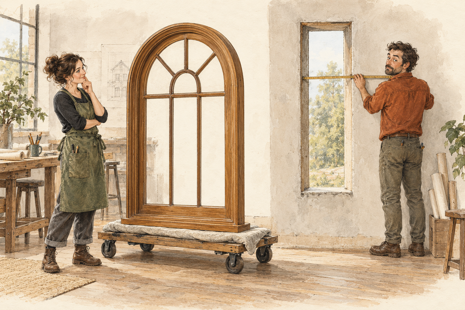
The small window example below isolates that distinction. Two frames can look identical before an edit. Stretch one horizontally and its vertical members become thicker. Change the other through a width parameter and its 60 mm frame stays 60 mm. Both operations do what they were told. The instructions describe different designs.
The issue grows with the assembly. A wider cabinet may need longer shelves, redistributed doors, and hardware that stays a fixed distance from each edge. Without authored relationships, the designer becomes the change-propagation system. Very flexible. Difficult to cache.
History, constraints, and procedural modeling already let us express such relationships. The challenge is making them easier to create, inspect, and combine with direct editing. A useful workspace should make the scope of an edit clear: this occurrence, every instance of the same definition, or the rule that generates them. A local exception should survive the next regeneration.
Propagation also has limits. A host face may disappear. Two constraints may become impossible to satisfy together. The useful response is to identify what lost its reference and help repair it. Quietly attaching the feature to some other convenient face can turn a visible modeling error into a hidden design error.
AI could help author and explain these relationships, then propose changes we can inspect in the model. The controls, the geometry, and the explanation should refer to the same thing. For that to feel useful, those interactions also have to happen at the pace of thinking.
02 / Identical now. Different on the next edit.
Stretch the geometry
Sides: 60 mm
Top / bottom: 60 mm
Preserve the frame
Sides: 60 mm
Top / bottom: 60 mm
07 / 12
Iteration includes everything between two decisions.
The time between ‘perhaps like this’ and ‘no, the other way’ matters. It includes finding the command, expressing the change, waiting for computation, inspecting the result, and repairing whatever broke. Making one part of that loop faster can leave the rest untouched.
Some of the cost comes from useful complexity. Autodesk’s Revit performance guidance identifies complex geometry, parametric relationships, and constraints among the factors that affect performance. That is not an argument against structured models. It is a reason to care about how much work each edit triggers. AI can add another wait if every adjustment sends the whole task back through generation.
Some of the cost is interaction. Can I select the part I mean? Find the value driving it? Compare an alternative without losing the original? Tell whether the result is current? Undo the change without unwinding five other decisions? These details determine how many ideas are cheap enough to try.
A better loop needs responsive previews, updates limited to what actually changed, clear edit scope, and dependable undo. It should reuse valid work and explain failures in a way that gives us a next step. A refusal with a useful diagnosis can save more time than a fast, confident mistake.
The figure is a schematic, not a speed benchmark. Its point is that inspection and revision belong inside the design process. Faster iteration gets us to a candidate worth keeping. The next question is whether that candidate can meet the demands of the real object.
03 / The whole edit loop
Express
Point to the window and specify the change. Decide what should stay fixed.
08 / 12
More detail should mean more understanding.
A detailed model is not simply one with more geometry. A chair can have beautifully rounded edges while its joints remain unresolved. A panel can have accurate dimensions while its fasteners collide with something behind it. The missing detail is a decision about how the object works.
Parts have roles, materials, connections, and limits. Stock thickness, joint allowances, moving clearances, and the way one component meets another can all affect the geometry. Keeping those relationships in the model makes the detail useful when the design changes. Leaving them in someone’s head makes that person’s holidays a project risk.
Geometric constraints and engineering checks are different kinds of knowledge. Keeping a bracket’s faces parallel does not establish that it can carry a load. A closed solid does not establish that a chosen process can manufacture it. Those conclusions need relevant assumptions, evidence, and, where appropriate, specialist judgment.
The opportunity is to connect requirements to the model: which value drives a detail, which check has been performed, and which question remains unresolved. AI can help explain and manage that information. Its explanation does not substitute for the check.
That is how a rough intention can grow into a highly detailed model with meaning. And once other people need to use it, that meaning has to survive the handoff.
09 / 12
Sharing the shape is only part of the handoff.
A client may need to inspect a proposal and comment on it. A colleague may need to revise an assembly. A fabricator may need geometry, dimensions, tolerances, and an unambiguous revision. These are different handoffs. Sending everyone the same attractive viewport does not settle them.
CAD already has serious tools for collaboration. Onshape’s versions and branching support controlled revisions and alternative directions. That addresses an important part of working together. Another part is whether the recipient can continue the design logic, particularly when the work moves between applications.
Onshape’s import documentation makes the distinction concrete: imported CAD from another system does not bring its original feature tree. The resulting geometry can still be useful, and direct edits or new features can still be added. But receiving a solid is different from receiving the original recipe for changing it.
Reusable work needs that recipe, or a useful interface to it: controls, allowed inputs, and relationships that continue to hold. In the example below, several windows share one width until we give one a local override. This is a small demonstration of a broader question: can I reuse a design, adapt one instance, and still benefit from improvements to the shared definition?
The same concern reaches drawings, quantities, and other outputs. Which revision do they describe? What updates when the model changes? A component that can be reused with understandable limits is more valuable than one that merely arrives intact. Every handoff should preserve as much useful work as the next person needs.

04 / One rule, with room for an exception
Window 1
1200 mm
Shared width
Window 2
1200 mm
Shared width
Window 3
1200 mm
Shared width
10 / 12
The scene could become the center of creative AI.
There is a larger reason to care about preserving that work. I think solving reliable, editable 3D generation is the most important next step for creative AI. Its value reaches into image generation, video, games, filmmaking, architecture, and product design: all the places where we need to decide what exists, then control how it appears or behaves.
A scene can hold those decisions together: which objects exist, their dimensions and positions, their materials, the lights, the cameras, and how things move over time. Images and shots can then draw on the same underlying description. The scene becomes a place to keep creative decisions, revise them, and use them again.
For image generation, that means being able to place a product, choose a viewpoint, and establish its proportions before asking for a visual treatment. Adobe’s Scene to Image already uses a constructed 3D scene to guide composition, camera angle, and depth. A rough blockout can be enough for composition; an accurate product model matters when the product itself must stay recognizable and correct. Six campaign images should not require the chair to reapply for its fourth leg six times.
For video and filmmaking, the same idea extends across time. We want to move a camera through a set, return to an earlier angle, and keep the objects and their positions consistent. NVIDIA’s GEN3C research uses an explicit 3D cache to guide video generation and camera movement. It is a bounded demonstration of how spatial information can improve control and consistency, rather than asking a video model to infer the whole arrangement again from each request.
For games, the scene also has to support interaction. The door needs a position, an opening motion, and appropriate collision geometry; a picture of a convincing door cannot supply those decisions. For architecture and design, the same model could connect the plan, the walkthrough, the material study, and the detailed component. Change an opening in the design, and the presentation should continue to describe that design. The renderer should not become a second architect with different measurements.
Film and game production already organize work around shared scenes. OpenUSD supports composing assets and exchanging scene information across tools, including geometry, shading, lighting, and physics. The opportunity for AI is to make this kind of structured creation easier to enter and develop, then make the resulting scene useful to generative workflows too. A scene format helps carry the work; it does not create the model or resolve its design for us.
This is my bet: for visual work that needs repeatable spatial control, the editable scene will become the most valuable thing we keep. A finished image captures one view. A well-structured scene can support another view, another shot, another material, or another medium while preserving the decisions we already made. Generating that scene well would improve much more than the first 3D result.
Not every illustration needs a 3D model. And a scene used as a reference does not guarantee that a generative model will obey it. We still need to distinguish fixed geometry from suggested appearance, inspect the output, and catch departures from the design. The more precise the creative control we want, the more valuable an explicit, editable description of the world becomes.
That makes ease of modeling a much larger issue. If creating and revising the scene remains specialist work, that control stays expensive. Making the scene approachable is how more people get to direct the result.
11 / 12
The workspace should grow with the design.
A scene that carries this much work needs a workspace that helps it develop. Begin with a form you can explore freely. Add dimensions and relationships as they become useful. Develop parts into detailed, reusable systems. Keep the rules understandable, the edits inspectable, and the requirements connected as the work moves toward review and delivery.
Direct and procedural modeling should be able to help each other. Drag one part when that is the clearest way to work. Change a rule when a hundred parts should follow. Ask an assistant to help with either. The generated result should remain part of the model you can edit, rather than becoming a separate artifact to rebuild.
That gives AI a continuing role: help make the first model, develop its details, explore alternatives, and explain dependencies. Sketches, selections, dimensions, and words can contribute to the same conversation. We should be able to inspect a proposed change and carry on from it. The useful unit of progress is a design we can continue working on.
This is a demanding standard. How easy is it to begin? How far can the detail go? What survives a change? How quickly can we try another direction? What can the next person reuse? A new tool has to earn its place across that process.
12 / 12
That is why we’re building Eskiz.
We’re building Eskiz: a new approach to 3D modeling, enhanced by AI collaboration.
The ambition is to move from an intention to highly detailed models, with the freedom to explore, the structure to make changes propagate, and an easier way to iterate. We want direct modeling, reusable logic, and AI assistance to work together, so the model can become more capable as the design develops.
That ambition draws on the work we’ve been doing on procedural design and editable modeling systems. There is a lot underneath it. We’ll leave the machinery for future posts and show what it means through actual design work.
Starting now, we’ll share details and progress weekly as we work toward the reveal. You can join the Eskiz waitlist to follow along.
We want more of the work between an idea and a finished design to be design work. That is what we’re building toward.